


Is there an equivalent of Maya ccmesh (Catmull-Clark mesh) object in Softimage?
I tried the subdivision mesh with Catmull-Clark rule but I don't think it is understood by mental ray as a ccmesh object.
Advice appreciated.
Cheers!
Daniel
CCMESH and PTex in Softimage 2013
-
Daniel Brassard

- Posts: 878
- Joined: 18 Mar 2010, 23:38
- Location: St. Thomas, Ontario
- Contact:
CCMESH and PTex in Softimage 2013
Last edited by Daniel Brassard on 01 Aug 2012, 18:39, edited 2 times in total.
$ifndef "Softimage"
set "Softimage" "true"
$endif
set "Softimage" "true"
$endif
Re: CCMESH
ccmesh needs to be nativly integrated in xsi, so have to call ad for this.
-
Daniel Brassard
- Posts: 878
- Joined: 18 Mar 2010, 23:38
- Location: St. Thomas, Ontario
- Contact:
Re: CCMESH
Thanks Kzin,
Time to dust up the shader books and do some shader programming then!
Cheers!
Dan
Time to dust up the shader books and do some shader programming then!
Cheers!
Dan
$ifndef "Softimage"
set "Softimage" "true"
$endif
set "Softimage" "true"
$endif
-
Daniel Brassard
- Posts: 878
- Joined: 18 Mar 2010, 23:38
- Location: St. Thomas, Ontario
- Contact:
Re: CCMESH
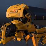
I had the time to revisit this subject lately and after a few frustrating test, I got it finally working.
What I did is program in C++ the Cattmull-Clark mesh example of the Mental Ray manual.
So here is the Hexacylinder (less the crease) in glorious render.
What I did is program in C++ the Cattmull-Clark mesh example of the Mental Ray manual.
So here is the Hexacylinder (less the crease) in glorious render.
- Attachments
-
$ifndef "Softimage"
set "Softimage" "true"
$endif
set "Softimage" "true"
$endif
-
Daniel Brassard
- Posts: 878
- Joined: 18 Mar 2010, 23:38
- Location: St. Thomas, Ontario
- Contact:
Re: CCMESH
Then it dawn on me to try one of the PTEX file because Mental Ray render Ptex object that are built on CCMesh. So I took the nonquad obj and hardcoded it as a ccmesh.
Then, as a proof of concept, I attached a PTex file using the mib_Ptex_Lookup node borrowed from Maya, and hook-it up to the diffuse port of the phong node and here is the result.
Now to change the code to accept any low resolution object via the UserDataBlob!
Whooahhhhh!
Nothing stopping me now!
Dan
- Attachments
-
-
Last edited by Daniel Brassard on 31 Jul 2012, 17:59, edited 1 time in total.
$ifndef "Softimage"
set "Softimage" "true"
$endif
set "Softimage" "true"
$endif
-
Hirazi Blue

- Administrator
- Posts: 5107
- Joined: 04 Jun 2009, 12:15
Re: CCMESH and PTex
Keep it up, I'm rooting for you!!! 
The only thing I can add myself, are unhelpful smilies, I'm afraid
The only thing I can add myself, are unhelpful
Stay safe, sane & healthy!

Re: CCMESH and PTex
hey Daniel, looks cool but... what does it do? 
I mean, what is the difference between this and the regular subdivision? Besides obviously supporting ptex, which is great!
I mean, what is the difference between this and the regular subdivision? Besides obviously supporting ptex, which is great!
Gustavo Eggert Boehs
Blog: http://www.gustavoeb.com.br/
Blog: http://www.gustavoeb.com.br/
-
Daniel Brassard
- Posts: 878
- Joined: 18 Mar 2010, 23:38
- Location: St. Thomas, Ontario
- Contact:
Re: CCMESH and PTex
Quoting from the MR manual:I mean, what is the difference between this and the regular subdivision? Besides obviously supporting ptex, which is great!
My test is done with the registry modification (so I know it work). Next to test the bary parameter.Catmull-Clark Mesh Geometry
Mental Ray provides a simplified and fast subdivision algorithm which is optimized for smoothing of arbitrary polygon meshes: the polygons in such a mesh can have an arbitrary number of edges.
A Catmull-Clark polygon mesh (ccmesh) is defined very similar to a regular polygon mesh, however it is further subdivided to get a smooth limit surface.
There are two main differences between a ccmesh and a subdivision surface:
1. A ccmesh cannot define hierarchies, and
2. A ccmesh can define polygons with an arbitrary number of edges, not just triangles and quads.
In the ccmesh subdivision process, each polygon is split into quadrilaterals using generalized Catmull-Clark subdivision rules. Mixed meshes consisting only of triangles and quads are directly subdivided using specialized rules. CC Subdivision rules are applied to both positions and texture coordinates for highest mapping quality.
Similar to subdivision surfaces a fractional sharpness value can be assigned to the polygon edges and, vertices can be tagged with a corner feature. The sharpness values introduce a local crease on the surface.
A ccmesh representation is well suited for fine displacement, because it does not suffer from inherent artifacts when displacing coarse polygon meshes.
Note: Mental Ray performs displacement mapping during computation of the limit surface, using a single approximation setting for the entire tessellation.
Ptex Support
The Ptex texture mapping system and file format developed by Walt Disney Animation Studios is now supported for rendering of ccmesh subdivision surface geometry. The new base shader mib_ptex_lookup is provided that performs lookup of the texturing information at render time.
To use Ptex, the ccmesh use the barycentric coordinates of the polygons locally, using the bary parameter of the ccmesh, or globally using the rayrc/ray3rc registry modification recommended in the MR Manual.
Last edited by Daniel Brassard on 31 Jul 2012, 18:02, edited 1 time in total.
$ifndef "Softimage"
set "Softimage" "true"
$endif
set "Softimage" "true"
$endif
-
Daniel Brassard
- Posts: 878
- Joined: 18 Mar 2010, 23:38
- Location: St. Thomas, Ontario
- Contact:
Re: CCMESH and PTex
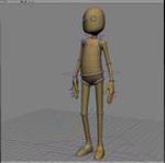
Simply speaking the ccmesh is a simple, faster subds, well suited to take input from a low resolution polygon mesh (created in 3D Coat, ZBrush or Mudbox). The ccmesh becomes your "limit surface" where you would apply the high res mapping, the texture mapping, bump mapping, normal mapping even vector displacement mapping to get your final model at render time.
Check this video from Pixar. When he talk about the smooth limit surface ... think ccmesh.
http://vimeo.com/17828592
Dan
Check this video from Pixar. When he talk about the smooth limit surface ... think ccmesh.
http://vimeo.com/17828592
Dan
$ifndef "Softimage"
set "Softimage" "true"
$endif
set "Softimage" "true"
$endif

Re: CCMESH and PTex
The 'corner feature' would be great to control. I *ahem* use Maya a lot to render and the lack of control over UV border smoothing for verts with a valence of two is something that has always bugged me. I don't think you can control that in Softimage either, right? It is a Mental Ray feature that is just not integrated. In Mudbox you can use an environment variable to get that kind of uv border smoothing which Renderman people enjoy. It would be great to be able to smooth like that in Mudbox, generate maps and then know that they are going to match up in MR. Any thoughts about this? Or too off topic..? No worries either way.
-Nick
-Nick
-
Daniel Brassard
- Posts: 878
- Joined: 18 Mar 2010, 23:38
- Location: St. Thomas, Ontario
- Contact:
Re: CCMESH and PTex
Hi Nick,
MR give you the possibility to tag vertices as corner vertices and/or crease. So theoretically, you could control the vertices by tagging them and passing the information to MR.
I don't know if this is the same as make hard edge in Softimage, my knowledge is limited on this one.
The two shape created above are a good test for these parameters: the hexacylinder has a crease attribute that would change the shape closer to a rounded cylinder and the nonquad could have its corner assigned with a "corner" attribute to make it more square. I don't know what will be the effect on the Ptex texture. I'll test that tonight and post the results.
Dan
Last edited by Daniel Brassard on 01 Aug 2012, 04:39, edited 1 time in total.
$ifndef "Softimage"
set "Softimage" "true"
$endif
set "Softimage" "true"
$endif
Re: CCMESH and PTex
Hi Daniel,
Thanks for the reply!
My knowledge on this is in Softimage is limited as well but it has been something I have always followed the progress of as I am a modeler/texture artist. This was brought up before here: http://www.si-community.com/community/v ... =10&t=2389 but the discussion never went anywhere. The thread might be useful though, so check it out.
Also, here is a post on the area about what I am talking about and it has some good illustrated examples of the different UV border smoothing that is going on in different applications. See here: http://area.autodesk.com/forum/autodesk ... omparisons. Modo seems to have this flexibility.
BTW - I am mainly concerned with what is going on with UVs here..I know you are going to explore what happens with the geometry as well but if you come across any interesting tidbits specifically on the UVs I would love to see the results. Not sure if the two are mutually exclusive or not in this case.
Anyhow, great work! Looking forward to seeing how far you go with this. Thanks,
-Nick
-
Daniel Brassard
- Posts: 878
- Joined: 18 Mar 2010, 23:38
- Location: St. Thomas, Ontario
- Contact:
Re: CCMESH and PTex
Thanks Nick for the information, that may prove useful at some point in time.
As a reference, here is what the MR Manual says about the CCMesh:
http://docs.autodesk.com/MENTALRAY/2013 ... clark.html
As a reference, here is what the MR Manual says about the CCMesh:
Quoted from here:A corner features may be associated with vertices by specifying corner behind the regular vertex definition:
v vec_ref [ tex_list ] [ m motion_ref ] [ corner [ level level ] ]
Here vec_ref is the reference of a position, tex_list is a list of texture coordinates and corresponding coordinate indices, and motion_ref is an optional motion vector. Up to 15 motion vectors may be specified for each vertex.
The optional vertex feature follows, and an optional level can be specified if the feature is active on a level above vertex definition level.
The polygon statement specifies the total number of polygons which are defined in the mesh, the vertex statement specifies the total number of vertices used by the polygons.
The optional crease statement allows specification of crease edges. If the crease statement is given, then for each polygon edge a floating point sharpness values follows in the sharpness_list. Any edge not creased in this list must be given with a zero sharpness.
http://docs.autodesk.com/MENTALRAY/2013 ... clark.html
$ifndef "Softimage"
set "Softimage" "true"
$endif
set "Softimage" "true"
$endif
Re: CCMESH and PTex
One more thing..I brought this up on the Nvidia Mental Images forum here: http://forum.mentalimages.com/showthrea ... roximation Their replies were what I thought - MR supports tagging as per the links you just posted but it is not integrated in Maya (Not sure about Softimage).
Might help also. Good luck!
-N
Might help also. Good luck!
-N
-
Daniel Brassard
- Posts: 878
- Joined: 18 Mar 2010, 23:38
- Location: St. Thomas, Ontario
- Contact:
Re: CCMESH and PTex
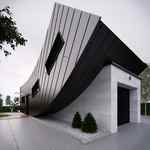
After some tests, I can confirm that influencing the polygons with the "crease" attribute or the corner vertices is doable.
Here some proof of concept.
The hexacylinder has a crease attribute on the polygons at the top and bottom cap, making the haxacylinder more like a cylinder.
The second pictures is the nonquad plane. I tagged vertex(0), bottom left, with the corner attribute, making the corner square compared to the other more rounder corners.
So it is just a matter of coding some form of tagging for the points to make them corners and polygons for crease.
Dan
- Attachments
-
-
$ifndef "Softimage"
set "Softimage" "true"
$endif
set "Softimage" "true"
$endif
Re: CCMESH and PTex in Softimage 2013
Excellent work - you nailed it. A good way to tag would be to have a modified selection tool where you can select a vert, edge, face to apply the crease to and then MMB (or some hotkey combo) drag to set a value between 0-1.
I would love to see what happens to UVs in certain scenarios and would be happy to prep some test scenes if you like.
I know that the texture coordinates are interpolated by default and that a per face (linear) result wouldn't look good - so is there a way to create schemes to control what gets interpolated and what doesn't? I looked here: http://docs.autodesk.com/MENTALRAY/2013 ... ode88.html and there is a section called Texture Space Interpolation that looks like it gives you options. Not sure this is where you are going with this so sorry to keep on with this. It's been a thorn in peoples sides for a while now though so I figured anyone who has gotten as far as you have might be able to throw in control for this also.
Good stuff, look forward to seeing how this goes,
-Nick
Who is online
Users browsing this forum: No registered users and 40 guests